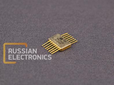
564TM2V INTEGRATED CIRCUIT
Dual D-type flip-flop
CMOS Technology
General Characteristics:
Supply voltage range from 4,2 V to 15,0 V.
Limit supply voltage up to18,0 V.
Nominal operating temperature ranges from -60 °Сto + 125 °С.
Turn-on and turn-off delay time ≤420 ns at VDD = 5,0 V, CL = 50 pF, T = 25 °C.
Low level output voltage ≤0,01 V at VDD = 5,0 V, T = 25 °C.
High level output voltage ≥4,99 V at VDD = 5,0 V, T = 25 °C.
Low level output current ≥1,0 мАat VDD = 10 V, VO = 0,5 V, T = 25 °C.
High level output current ≥/-1,0/ mA at VDD = 10 V, VO = 9,5 V, T = 25 °C.
Table 1. Pin Description
| Pin No. | Symbol | Function |
| 1 | Q1 | Output1 |
| 2 | _______ Q1 | Output1 Inverted |
| 3 | C1 | Clock1 Input |
| 4 | R1 | Reset1 Input |
| 5 | D1 | Data1 Input |
| 6 | S1 | Set1 Input |
| 7 | 0V | Common |
| 8 | S2 | Set2 Input |
| 9 | D2 | Data2 Input |
| 10 | R2 | Reset 2 Input |
| 11 | C2 | Clock2 Input |
| 12 | ____________ Q2 | Output2 inverted |
| 13 | Q2 | Output2 |
| 14 | VCC | Supply Voltage |
Table 2. Truth Table
| C | D | R | S | Q | __ Q | L - low level, H - high level, X - don’t care , ↑ - transition from low level to high level, ↓ - transition from high level to low level. |
| ↑ | L | L | L | L | H | |
| ↑ | H | L | L | H | L | |
| ↓ | X | L | L | Q | Q | |
| X | X | H | L | L | H | |
| X | X | L | H | H | L | |
| X | X | H | H | H | H |
Table 3. Electrical Parameters
| Parameter description, unit of measure, conditions | Symbol | Rated parameter | Ambient temperature, oC | ||
| min | max | ||||
| 1. Low level output voltage, V at: VDD= 5,0 V; 10,0 V | VOL | - | 0,01 | 25±10 -60 | |
| - | 0,05 | 125 | |||
| 2.High level output voltage, V at: VDD = 5,0 V VDD = 10,0 V | VOH |
| - | 25±10 -60 | |
| 4,95 | - | 125 | |||
| 9,99 | - | 25±10 -60 | |||
| 9,95 | - | 125 | |||
| 3.Maximum low level output voltage, V at: VDD = 5,0 V; VIH = 3,5 V; VIL = 1,5 V VDD = 5,0 V; VIH = 3,6 V; VIL = 1,5 V VDD = 5,0 V; VIH = 3,5 V; VIL = 1,4 V VDD = 10,0 V; VIH = 7,0 V; VIL = 3,0 V VDD = 10,0 V; VIH = 7,1 V; VIL = 3,0 V VDD = 10,0 V; VIH = 7,0 V; VIL = 2,9V | VOL max | - | 0,8 | 25±10 -60 125 | |
| - | 1,0 | 25±10 -60 125 | |||
| 4. Maximum high level output voltage,V at: VDD=5,0 V; VIH= 3,5V; VIL=1,5 V VDD=5,0V; VIH= 3,6 V; VIL=1,5 V VDD=5,0V; VIH= 3,5 V; VIL=1,4 V VDD=10,0V; VIH= 7,0 V; VIL=3,0 V VDD=10,0V; VIH= 7,1 V; VIL=3,0 V VDD=10,0V; VIH= 7,0V; VIL=2,9 V | VOH max | 4,2 | - | 25±10 -60 125 | |
| 9,0 | - | 25±10 -60 125 | |||
| 5. Low level input current, µA , at: VDD = 15,0 V | IIL | - | / - 0,1 / | 25±10 -60 | |
| - | / - 1,0 / | 125 | |||
| 6. High level input current, µA , at: VDD = 15,0 V | IIH | - | 0,1 | 25±10 -60 | |
| - | 1,0 | 125 | |||
| 7. Low level output current, mA, at: VDD = 5,0 V; VO = 0,5 V VDD = 10,0 V; VO = 0,5 V | IOL | 0,5 0,6 0,3 | - - - | 25±10 -60 125 | |
| 1,0 1,2 0,7 | - - - | 25±10 -60 125 | |||
| 8. High level output current, mA, at: VDD = 5,0 V; VO = 4,5 V VDD = 10,0 V; VO = 9,5 V | IOH | / - 1,0 / / - 1,0 / / - 1,0 / | - - - | 25±10 -60 125 | |
| / - 1,0 / / - 1,0 / / - 1,0 / | - - - | 25±10 -60 125 | |||
| 9. Supply current, µA, at VDD=5,0V VDD=10,0 V VDD=15,0V | IDD | - - - | 1,0 1,0 30,0 | 25±10 -60 125 | |
| - - - | 2,0 2,0 60,0 | 25±10 -60 125 | |||
| - - - | 4,0 4,0 120,0 | 25±10 -60 125 | |||
| 10.Dynamic supply current, mA, at VDD=10 V, VIH=10,0 V, VIL=0 V; f=100 kHz; CL=50 pF | IDDT | - | 0,17 | 25±10 | |
| 11. Propagation delay time (turn-on), ns, at: VDD=5,0 V, CL=50 pF VDD=10,0 V, CL=50 pF | tPHL | - - - | 420 420 590 | 25±10 -60 125 | |
| - - - | 159 150 210 | 25±10 -60 125 | |||
| 12. Propagation delay time (turn-off), ns, at: VDD=5,0 V, CL=50 pF VDD=10,0 V, CL=50 pF | tPLH | - - - | 420 420 590 | 25±10 -60 125 | |
| - - - | 150 150 210 | 25±10 -60 125 | |||
| 13. Input capacitance, pF, at: VDD=10,0 V | CI | - | 7,5 | 25±10 | |
Table 4. Absolute maximum operating limits
| Parameter description, unit of measure, conditions | Symbol | Rated parameter | Operating limit exposure time, ms, max | |||
| allowable limit | limit load operation | |||||
| min | max | min | max | |||
| Supply voltage, V | VDD | 4,2 | 15,0 | minus 0,5 | 18,0 | - |
| Input voltage, V | VI | minus 0,2 | VDD + 0,2 | - | - | - |
| Maximum input capacitance, pF | CL max | - | 50,0 | - | 1000 | - |
| Maximum output current, mA | IO max | - | - | - | 10,0 | - |
Normal conditions service life – min100000 hours
Light conditions service life at VDD=5 V± 10 %– min 120000 hours
Weight: max1,0 g (package401.14-5)


