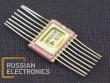
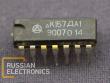
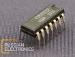
K1156EU1
Multipurpose impulse voltage regulator.
The microcircuit is a set of functional elements for a step-up orbuck regulator or inveter.
Case type: K1156EU1T – metal-ceramic,type 4112.16-3, K1156EU1 – plastic, type 283.16-2.
Electrical parameters(at ambient air temperature -60..+125 oC)
| Parameter name | Letter symbol | Pin | Rated value | Measurement mode | |
| not less than | not more than | ||||
| Residual voltage, V pins 15 and 16 engaged pins 15 and 16 disengaged | UDC | 16 |
- - |
2.0 1.5 | UCC1=3 V Is=1000 mA |
| Reference voltage, V | UREF | 8 | 1.18 | 1.31 | UCC1=3..40 V I0=-1 mA |
| Operational amplifier low level output voltage, V | UOL | 4 | - | UCC3 + 2.0 | UCC1=20 V UCC2=5 V UCC3=-5 V I0 = 5 mA |
| Operational amplifier high level output voltage, V | UOH | 4 | UCC3 - 2.0 | - | UCC1=20 V UCC2=5 V UCC3=-5 V I0 = - 50 mA |
| Operational amplifier zero point offset voltage, mV | UI02 | 6,7 | -50 | +50 | UCC1=20 V UCC2=20 V UCC3=-20 V
|
| Comparator zero point offset voltage, mV | UI02 | 9, 10 | -50 | +50 | UCC1=40 V
|
| Current protection cut-off voltage, mV | Up | 14 | 200 | 500 | UCC1=5 V
|
| Diode forward voltage, V | UF | 2 | - | 2.0 | IF=1000 mA |
| Operational amplifier input current, µA | I11 | 6,7 | - | 1.5 | UCC1=20 V UCC2=20 V UCC3=-20 V |
| Comparator input current, µA | I12 | 9,1 | - | 1.5 | UCC1=40 V |
| Current consumption (excl. operational amplifier), mA | ICC1 | 13 | - | 5.0 | UCC1=40 V |
| Operational amplifier current consumption, mA | ICC2 | 5 | - | 2.5 | UCC1=20 V UCC2=20 V UCC3=-20 V |
| Timing capacitance discharge current, µA | IDCH | 12 | 175 | 400 | UCC1=5..40 V |
| Timing capacitance charge current, µA | ICH | 12 | 15 | 35 | UCC1=40 V |
| Output leakage current, µA | ILO | 16 | - | 20 | UCC1=40 V US=40 V |
| Diode leakage current, µA | IL | 2 | - | 20 | U1=-40 V (anode voltage) |
| Voltage instability, %/V | KUI | 8 | - | 0.025 | UCC1=3..40 V IO=-1.0 mA |
| Current instability, %/mA | KUO | 8 | - | 0.1 | UCC1=5V IO=-(1..10) mA |
Notes:
UCC3 – stabilized voltage at pin 11
Positive current direction – into the circuit.