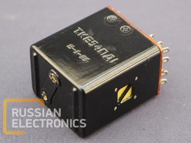
* Pictures are placed for illustration purpose only. Appearance of real component may differ.
Electromagnetic relays for AC and DC circuits.
Relays are divided by: rated control voltage; operating current type; main contacts rated current; contact number and type; maximum allowed ambient air temperature; extra features
Annotation breakdown
[1st element] – rated control voltage: T – 27 V DC, P – 18 V DC, S – 115 V AC
[2nd element] – relay version: K – DC-operated switching relay; P – AC-operated switching relay
[3rd element] – main contacts rated current: letter – multiplicator:N – 0.1; E – 1; D – 10. Following number should be multiplied by the multiplicator
[ 1st digit] – 0 – the absence of independent NC contacts;
[2nd digit] – number of independent NO contacts; number+”P” – number of switching contacts
[*] – maximum ambient air temperature: 0 – 85 oC; 1 – 100 oC (in earlier versions OD – 85 oC; 1 – 100 oC; 1P – 150 oC)
[*][*] - extra features: G – sealed; A, B, M2 – upgraded versions
Main features
Relay is a device with switching contact groups operated by valve-type electromagnet.
Mounting method: wire mounting, soldering.
Relay is fastened by screws installed on the bottom of the cover.
Unsealed relays are ventilated through the cover holes, covered by the mesh.
Unsealed relays are subject to environmental impacts (humidity, temperature, air pressure). Sealed relays should be chosen to avoid that impacts.
In sealed relays switching contacts and some magnetic conductor details are enclosed in a separate welded compartment with dry air. In TKE21POGD relay the entire magnetic system with a coil is enclosed in that compartment
TKE22P1GB, TKE24P1GB, TKE26P1GB can be used together (making 2, 4 or 6 switching groups), have similar design and differ by dimensions and coil parameters
TKE22P1GA, TKE22PODGB can be used together (making 4 or 6 switching groups), have similar design and differ by dimensions and coil parameters.
SPE22PODGB, TPE22PODGB have similar design and differ by coil parameters and diode blocks for control current rectification.
TKN21POGM series 2, TKN21P1DG, TKE101ODG are for PCB mounting and should be fastened by epoxy adhesive and soldering.
| Version | Design | Ambient air temperature, oC | Rated contact voltage, V | Contact voltage range, V | Contact current range, A | Control voltage range, V | Opearting mode | Number of contact pairs | Switching durability, cycles* | Mass, g | ||||
| DC | AC 400Hz | AC 50..1100 Hz | DC | AC 50-1100 Hz | switching | front | ||||||||
| TKE52PD1 | non-sealed | -60..+100 | 27 | 16..30 | 20..220 | - | 0.05..5 | 24..30 | - | Continuous | 2 | - | 1·104 | 100 |
| TKE54PD1 | 4 | 140 | ||||||||||||
| TKE56PD1 | 6 | 180 | ||||||||||||
| TKE52PK1 | 17.5..30 | Short-time | 2 | 100 | ||||||||||
| TKE54PK1 | 4 | 140 | ||||||||||||
| TKE56PK1 | 6 | 180 | ||||||||||||
| TKD12PD1 | 0.1..10 | 24..30 | Continuous | 2 | 170 | |||||||||
| TKD12PK1 | 17.5..30 | Short-time | ||||||||||||
| TKN21PODGM series 2 | sealed | -60..+85 | 0.05..150 | 5..134 | 0.00001..0.25 | 24..30 | Continuous | 1 | 5·104 | 2.2 | ||||
| TKN21P1DG | -60..+100 | 0.2..30 | 0.001..0.25 | 16.5..30 | 6.3 | |||||||||
| TKE101ODG | -60..+85 | 17..30 | - | 0.05..1 | - | 1 | 3·104 | 6.5 | ||||||
| TKE21PODG | -60..+100 | 5..30 | 12..220 | 0.001..2 | 22..30 | 1 |
| 1·104 | 35 | |||||
| TKE22P1GB | - | 12..220 | 24..30 | 2 | 50 | |||||||||
| TKE24P1GB | 4 | 75 | ||||||||||||
| TKE26P1GB | 6 | 100
| ||||||||||||
| TKE24P1GA | 4 | |||||||||||||
| TKE26P1GA | 6 | 125 | ||||||||||||
| TKE52PODGB | -60..+85 | 20..200 | 0.05..5 | 2 | ||||||||||
| TKE52P1PGB | -60…+150 | 12..220 | ||||||||||||
| PKE52P1PGB | 12-16 | |||||||||||||
| TPE22PODGB | -60..+85 | 0.05..2 | - | 32..40 | 60 | |||||||||
| SPE22PODGB | 108..120 | |||||||||||||


