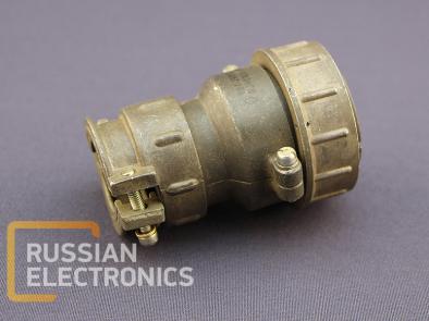
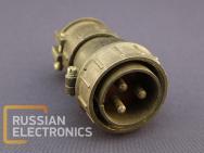
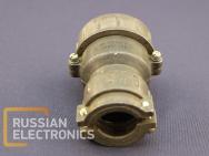
Connectors are suitable for use in DC and AC (with frequencies up to 2 MHz) electrical circuits at voltages up to 850 V. Connector consists of two units: a plug and a socket. SHR plugs and sockets are designed for installation either on equipment cases or on cables.
Panel-side of connector has either no outer shell, straight or angular shell. Cable-side connector has either a straight or angle shell.
Connectors are suitable for shielded or unshielded cables, suitability depends on the shell end nut construction. Contact diameters: 1.5 mm, 2.5 mm, 3.5 mm, 5.5 mm, 9.0 mm (contacts with 5.5 mm and 9.0 mm are extractable). Contacts are silver- or nickel-plated.
Connectors are built for indoor and outdoor installation (considering enclosure protection is provided) in boreal-climate design.
Connectors comply with specifications NCCS.433410.504TU (NCCS.434410.111TU) and can be connected with SHR connectors compliant with GEO.364.107 TU and 2RT-A connectors compliant with GEO.364.120 TU (ASHDK.434410.060 TU)
Connector annotation breakdown:
| SHR | 20 | P | 3 | E | G | 7 |
| Connector type | Design: Unit-side connector: P – without shell PK – straight shell SK – angular shell Cable-side connector: P – straight shell U – angular shell | Number of contacts | Type of shell end nut (1): E – for shielded cables N – for unshielded cables | Contacts type (2): Panel-side connector: SH – plug G – socket Cable-side connector: SH – socket G – plug | Contacts layout symbolic notation |
Notes:
- Unit-side connector without shell has no end nut. “E” is a dummy symbol in this case.
- Cable-side connector contact type is notated in accordance with a panel-side connector it suits.
- Left-banded cable-side plugs have an additional “L” symbol in annotation
Examples:
Unit- side plug SHR28P4ESH5-K
Cable-side socket SHR20P4ESH8-K
Electrical parameters:
| Contacts diameter, mm | 1.5 | 2.5 | 3.5 | 5.5 | 9 |
| Contact resistance (for silver-plated contacts), not more than, m? | 2.5 | 1 | 0..75 | 0.3 | 0.15 |
| Contact resistance (for nickel-plated contacts), not more than, m? | 5 | 2 | 1.5 | 0.75 | 0.6 |
Insulation resistance in regular climatic conditions 5000 M?
Peak voltage value 850 V
Reliability parameters
| Number of connection-disconnection cycles | 500 |
| Minimum lifetime | 1500 hours |
| Shelf life | 15 years |
Operational conditions
| Sinusoidal vibrations: | |
| Frequency range, Hz | 1-5000 |
| Acceleration m/s2 (g) | 300 (30) |
| Mechanical shock: | |
| Single, acceleration m/s2 (g) | 5000 (500) |
| Multiple, acceleration m/s2 (g) | 350 (35) |
Climatic factors
| Operating ambient temperature, oC | -60..+60 |
| Diminished air pressure, Pa (mm Hg) | 1.3?10-4 (1?10-6) |
Minimum lifetime at given connector temperature
| Minimum lifetime, h | Connector temperature, oC |
| 1000 | 110 |
| 2000 | 93 |
| 5000 | 85 |
| 7500 | 79 |
| 10000 | 75 |
| 15000 | 70 |
| 20000 | 66 |
| 25000 | 63 |
| 30000 | 61 |
| 40000 | 58 |
| 50000 | 55 |
| 80000 | 49 |
| 100000 | 47 |
| 130000 | 41 |
Contact overheat temperature dependency on ampere load
| Ampere load (in % of maximum) | Contact overheat temperature, oC |
| 90 | 44 |
| 80 | 38 |
| 70 | 33 |
| 60 | 27 |
| 50 | 22 |
You can order SHR40P3NG9 plug from us
Other products in Wires, connectors


