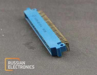
* Pictures are placed for illustration purpose only. Appearance of real component may differ.
SNO-51, SNO-52, SNO-53, SNO-54
Rectangular connectors for computing hardware, automated control systems and other equipment. Low-frequency connectors are designed for DC, AC (up to 3 MHz) and impulse circuits with voltages up to 250 V and current up to 2 A
Mounting method: PCB mounting and wire mounting (round and flat-strip conductors)
Climate version: all-climate
Connection types: push-pull and cut-in
Contact plating: gold, silver.
Annotation breakdown
Annotation example: SNO51 – 40 / 69x9-V 23 S
SNO – connector type
- SNO – for wire mounting,
- SNP – for PCB mounting
51 –version
- 51, 53 – silver (silver alloy) plated contacts,
- 52, 54 – gold (gold alloy) plated contacts
40 – number of contacts
- 8,
- 10,
- 20,
- 30,
- 60
69x9 – dimensions (length x width)
V – connector type
- V – plug,
- R – socket
23 – mounting method:
- 23 – angular PCB mounting with fastening,
- 14 – plug for wire mounting (soldering) with fastening,
- 2 – socket for wire mounting (soldering)
S – fastening brackets
Electrical parameters
| Maximum voltage,V at contact spacing 2,5mm at contact spacing 3,75mm | 150 250 |
| Maximum current per contact at 10% of max.load of other contacts,A | 2,2 |
| Rated current per contact, not more than ,A at contact spacing 2,5mm at contact spacing 3,75mm | 1,0 2,0 |
| Maximum short-pulsed current per contact, not nore than,A at contact spacing 2,5mm at contact spacing 3,75mm | 2 4 |
| Contact resistance,not more than,Ohm | 0,01 |
| Static instability of contact resistance ,not more than | 0,001 |
| Inter-contact capacitance,not more than ,pF at contact spacing 2,5mm at contact spacing 3,75mm | 3,0 2,5 |
| Insulation resistance ,MOhm at normal conditions after temporary temperature increasing after short-termed humidity increasing | 1000 50 20 |
You can order SNO53-60-23-2V plug from us
Other products in Wires, connectors


