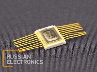
Eight-channel CMOS multiplexer
General Characteristics:
Supply voltage range from 4.2 Vto 15.0 V.
Limit supply voltage from -0.5V to18.0 V.
Nominal operating temperature ranges from -60 °С to + 125 °С.
Turn-on and turn-off delay time (from the control input to the switch output)≤ 720 nsatVCC = 5.0 V, VIL = 0 V, CL = 50 pF, RL=10.0 kΩ, T = 25 °C.
Voltage drop when the switch is open ≤ 600 mVatVCC1 = 5.0 V, VIH= 5.0 V, VIL = 0 V,
RL = 10.0 kΩ, T = 25 °C.
Input and output voltage limit value from -0.5 Vto (VCC + 0.5) V.
Table1.Pin Description
| Pin No. | Symbol | Function |
| 1 | X4 | Channel input/output |
| 2 | X6 | Channel input/output |
| 3 | Y | Output/Input |
| 4 | X7 | Channel input/output |
| 5 | X5 | Channel input/output |
| 6 | D | Disable input |
| 7 | VCC2 | Supply Voltage |
| 8 | 0V | Common |
| 9 | C | Control input |
| 10 | B | Control input |
| 11 | A | Control input |
| 12 | X3 | Channel input/output |
| 13 | X0 | Channel input/output |
| 14 | X1 | Channel input/output |
| 15 | X2 | Channel input/output |
| 16 | VCC1 | Supply Voltage |
Table2.TruthTable
| Logic inputs S Open chachachannek | Open channel | L- lowlevel; H- high level; X -don’t care.
| |||
| D | C | B | A | - | |
| L | L | L | L | Y-X0 | |
| L | L | L | H | Y-X1 | |
| L | L | H | L | Y-X2 | |
| L | L | H | H | Y-X3 | |
| L | H | L | L | Y-X4 | |
| L | H | L | H | Y-X5 | |
| L | H | H | L | Y-X6 | |
| L | H | H | H | Y-X7 | |
| H | X | X | X | All closed | |
Table 3.Electrical Parameters
|
Parameter description, unit of measure, conditions |
Symbol | Rated parameter | Ambient temperature, oC | ||||||||
| min | max | ||||||||||
| 1. Voltage drop in open state, mV, at: VCC1=5.0 V; VIH= 5.0 V; VIL= 0V; RL=10.0 kΩ | VC | - - - | 600 600 1200 | 25±10 -60 125 | |||||||
| VCC1=10.0 V; VIH= 10.0 V; VIL= 0V; RL=10.0 kΩ | - - - | 300 300 600 | 25±10 -60 125 | ||||||||
| 2. Low level input current, µA , at: VCC1=10.0 V; VIH= 10.0 V; VIL= 0V | IIL | - - - | / - 0.05 / / - 0.05 / / - 1.00 / | 25±10 -60 125 | |||||||
| VCC1=15.0 V; VIH= 15.0 V; VIL= 0V | - | / - 0.10 / | 25±10 | ||||||||
| 3. Highlevel input current,µA , at: VCC1=10.0 V; VIH= 10.0 V; VIL= 0V | IIH | - - - | 0.05 0.05 1.00 | 25±10 -60 125 | |||||||
| VCC1=15.0 V; VIH= 15.0 V; VIL= 0V | |||||||||||
| - | -0.10 | 25±10 | |||||||||
| 4. Supply current, µA, at: VCC1=10.0 V; VIH= 10.0 V; VIL= 0V | ICC | - - - | 10 10 300 | 25±10 -60 125 | |||||||
| VCC1=15.0 V; VIH= 15.0 V; VIL= 0V | - | 20 | 25±10 | ||||||||
| 5. Leakage current in closed state, µA, at: VCC1=10.0 V; VIH= 10.0 V; VIL= 0V | IL | - - - | 0.5 0.5 30.0 | 25±10 -60 125 | |||||||
| 6. Total leakage current in closed state, µA, at: VCC1=10.0 V; VIH= 10.0 V; VIL= 0V | IL∑ | - - - | 2 2 120 | 25±10 -60 125 | |||||||
| 7.Maximum leakage current in closed state, µA, at: VCC1 = 5,0 V; VIH = 3,5 V; VIL = 1,5 V VCC1 = 5,0 V; VIH = 3,6 V; VIL = 1,5 V VCC1 = 5,0 V; VIH = 3,5 V; VIL = 1,4 V | IL max |
- - - |
10 10 300 |
25±10 -60 125 | |||||||
| VCC1 = 10,0 V; VIH = 7,0 V; VIL = 3,0 V VCC1 = 10,0 V; VIH = 7,1 V; VIL = 3,0 V VCC1 = 10,0 V; VIH = 7,0 V; VIL = 2,9V | - - - | 10 10 300 | 25±10 -60 125 | ||||||||
| 8. Propagation delay time, turn-on (turn-off), ns,
at: VCC1=5.0 V; VIH= 5.0 V; VIL= 0V; CL= 50 pF; RL=10.0 kΩ | tPHL1 (tPLH1) |
- - - |
720 720 1000 |
25±10 -60 125 | |||||||
| VCC1=10.0 V; VIH= 10.0 V; VIL= 0V; CL= 50 pF; RL=10.0 kΩ | - - - | 320 320 450 | 25±10 -60 125 | ||||||||
at: VCC1=5.0 V; VIH= 5.0 V; VIL= 0V; CL= 50 pF; RL=10.0 kΩ | tPHZ (tPLZ) | - - - | 1000 1000 1400 | 25±10 -60 125 | |||||||
| VCC1=10.0 V; VIH= 10.0 V; VIL= 0V; CL= 50 pF; RL=10.0 kΩ | - - - | 400 400 560 | 25±10 -60 125 | ||||||||
| 8. Propagation delay time, turn-on (turn-off), ns,
at: VCC1=10.0 V; VIH= 10.0 V; VIL= 0V; CL= 50 pF; RL=10.0 kΩ | tPHL2 (tPLH2) | - - - | 30 30 42 | 25±10 -60 125 | |||||||
| 9. Control inputs capacitance, pF, at: VCC1 = 10.0 V | C | - | 10 | 25±10
| |||||||
| 10. Switch input capacitance, pF, at: VCC1 = 10.0 V | CI | - | 15 | 25±10
| |||||||
| 11. Switch output capacitance, pF, at: VCC1 = 10.0 V | CO | - | 90 | 25±10 -60 125 | |||||||
| 12.Switch transfer capacitance, pF, at: VCC1– VCC2 = 10.0 V | CI-O | - | 1 | 25±10 | |||||||
| |||||||||||
Table 4.Absolute maximum operating limits
| Parameter description, unit of measure, conditions | Symbol | Rated parameter | Operating limit exposure time, ms, max | |||
| allowable limit | limit load operation | |||||
| min | max | min | max | |||
| Supply voltage, V | VCC | 4.2 | 15.0 | minus 0.5 | 18.0 | - |
| Input voltage, V | VI | 0 | VCC | minus 0.5 | VCC + 0.5 | - |
| IC output voltage in the off state, V | VO | 0 | VCC | minus 0.5 | VCC + 0.5 | - |
| Input rise and fall times, ns at: VCC= 5.0 V VCC= 10.0 V VCC= 15.0 V | τrt, τft | - | 201) 201) 201) | - | 2) | - |
| Load capacitance, pF | CL | - | 501) | - | 3000 | - |
1) When measuring dynamic parameters.
2) Rise and fall times are not regulated.
Normal conditions service life at T= max 65+5 OC – min100000hours and 120000 hours in the following conditions: VCC from 5.0 to 10.0 V; CL< 500 pF; absence of limit operation; high ambient temperature - max 70OC.
Light conditions service life at VDD=5 V± 10 %– min 120000 hours
Weight: max1.7g


