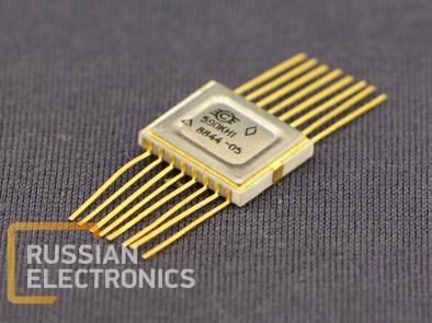
590KN1
Integrated circuit – 8-channel MOS-switch with decoder for voltages -5..5 V
Terminal assignment
| Terminal | Assignment | Terminal | Assignment |
| 1 | Analog input 1 | 9 | Analog input 8 |
| 2 | Analog input 2 | 10 | Analog output |
| 3 | Analog input 3 | 11 | - |
| 4 | Analog input 4 | 12 | Enable input |
| 5 | Analog input 5 | 13 | Address input 22 |
| 6 | Analog input 6 | 14 | Address input 21 |
| 7 | Analog input 7 | 15 | Address input 20 |
| 8 | GND | 16 | VCC |
Main electrical parameters (at +25±10 oC)
| Parameter | Not less than | Not more than | Notes |
| Analog input leakage current, nA | - | 50 | 1 |
| Analog output leakage current, nA | - | 50 | 1 |
| High-level control voltage, V | - | 1 | 1 |
| Low-level control voltage, V | - | 1 | 1 |
| Current consumption at low-level control voltage, mA | - | 3.5 | 1 |
| Current consumption at high-level control voltage, mA | - | 3.5 | 1 |
| Turn-on time, mks | - | 1 | 1, 2 |
| Resistance in on-state, Ohm | - | 200 500 | 1, 3 1, 4 |
Notes:
1. Power supply voltage 1 16.5..-13.5 V, power supply voltage 2 4.5..5.5 V
Low-level control voltage 0..0.8 V
High-level control voltage 3.6..5.5 V
Switching voltage -5..5 V
High-level control voltage and switching voltage not more than power supply voltage 2, high-level control voltage – not less than power supply voltage 2 – 0.9 V
2. Switching voltage 5 V, switching current 1 Ma, load resistance not more than 10 kOhm, load capacitance not more than 40 pF
3. Switching voltage 0..5 V
4. Switching voltage -5..0 V


