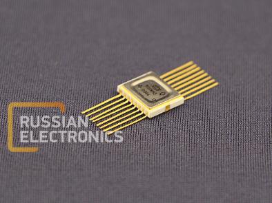
590KN3 Integrated circuit is an 8-channel (4×2) analog multiplexer-decoder designed to commutate analog signals voltage from minus 15 to 15 V.
PIN DESCRIPTION
| Pin Number | Function | Pin Number | Function |
| 1 | Control input 20 | 9 | Analog output B |
| 2 | Enable input | 10 | Analog input 4B |
| 3 | VDD2 | 11 | Analog input 3B |
| 4 | Analog input 1A | 12 | Analog input 2B |
| 5 | Analog input 2A | 13 | Analog input 1B |
| 6 | Analog input 3A | 14 | VDD1 |
| 7 | Analog input 4A | 15 | 0 V |
| 8 | Analog output A | 16 | Control input 21 |
ELECTRICAL PARAMETERS
at t = (25±10) °С
| Parameter, unit | Nominal value | Notes | |
| min | max | ||
| Analog input leakage current, nA | - | 50 | 1 |
| Analog output leakage current, nA | - | 70 | 1 |
| Low level control input current, µA | - | 0,2 | 1 |
| High level control input current, µA | - | 0,2 | 1 |
| Current consumption at high level control voltage, µA from a positive source from a negative source | - | 1000 10 | 1 |
| Current consumption at low level control voltage, µA from a positive source from a negative source | - | 10 15 | 1 |
| Connect time, ns | - | 300 | 1,2 |
| Open-stateimpedance, Ohm | - | 300 | 1,3 |
NOTES:
1. Supply voltage VDD1 from 13,5 to 16,5 V, VDD2 from minus 16,5 to minus 13,5 V, low level control voltage from 0 to 0,8 V, high level control voltage from 4 V to VDD1, commutating voltage from minus 15 to 15 V. High level control voltage shall not exceed VDD1, and absolute value VDD1, VDD2 shall exceed the absolute value of commutating voltage for at least 0,3 V.
2. Load impedance not more than 10 kΩ, load capacitance not more than 40 pF.
3. Commutating current– 1 mA.


