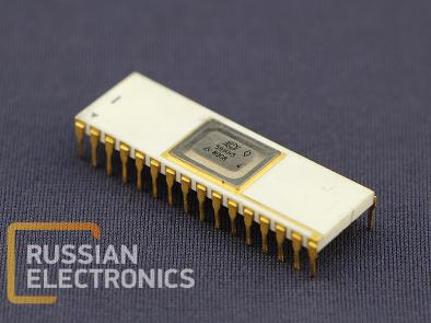
591KN3 Integrated circuit is a 16-channel analog signal multiplexer with a control circuit.
PIN DESCRIPTION
| Pin Number | Function | Pin Number | Function |
| 1 | VDD1 | 17 | - |
| 2 | - | 18 | Address input 21 |
| 3 | - | 19 | - |
| 4 | Analog input 16 | 20 | Address input 20 |
| 5 | Analog input 15 | 21 | Enable |
| 6 | Analog input 14 | 22 | - |
| 7 | Analog input13 | 23 | Analog input 1 |
| 8 | Analog input 12 | 24 | Analog input 2 |
| 9 | Analog input 11 | 25 | Analog input 3 |
| 10 | Analog input 10 | 26 | Analog input 4 |
| 11 | Analog input 9 | 27 | Analog input 5 |
| 12 | Common | 28 | Analog input 6 |
| 13 | - | 29 | Analog input 7 |
| 14 | Analog input 23 | 30 | Analog input 8 |
| 15 | Analog input 22 | 31 | VDD2 |
| 16 | - | 32 | Analog output |
ELECTRICAL PARAMETERS
at t = (25±10) °С
| Parameter, unit | Nominal value | |
| min | max | |
| Analog input leakage current, nA | - | 50 |
| Analog output leakage current, nA | - | 70 |
| Low level input current, µA | - | 0,2 |
| High level input current, µA | - | 0,2 |
| Supply current at high level control voltage, µA | - | 1000 |
| Supply current at low level control voltage, µA | - | 100 |
| Connect time, ns | - | 300 |
| Open-stateimpedance, Ohm | - | 270 |
* At supply voltage (VDD1) from minus 13,5 to 16,5 V, (VDD2) from minus 16,5 to minus 13,5 V, low level control voltage from 0 to 0,8 V, high level control voltage from 4 V to VDD1, commutating voltage from minus 15 to 15 V. High level control voltage shall not exceed VDD1, and absolute value VDD1, VDD2 shall exceed the absolute value of commutating voltage for at least 0,3 V. Load impedance shall not be more than 10 kΩ, and load capacitance shall not be more than 40 pF at connect time measurement. Impedance shall be measured at commutating voltage 1 mA.


