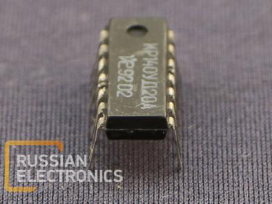
KR140UD20A
Dual-channel operational amplifier with high channel separation level (-85 dB). The circuit has an extra input for balancing capacitor. The balancing capacitor, connected between this input and inverting input increases the slew rate to 10 V/mks.
Ambient air temperature -60..+125 oC
Case types: 201.14-10, N01.16-2V
Operational limits
| Parameter name | Edge operating conditions | Marginal conditions | Marginal conditions duration | ||
| not less than | not more than | not less than | not more than | ||
| Power supply voltage, V | ±5.0 | ±18.0 | ±5.0 | ±20.0 | 2 h |
| Common-mode input voltage (at input voltage ±15 V, if less than equals power supply voltage | ±10 | ±15 | 1 min with pulse rate 30 min | ||
| Load resistace, kOhm | 2.0 | 1.8 | |||
Warranty lifetime in normal conditions 100000 h
Warranty lifetime in benign conditions 120000 h
Y-percentile time to failure (Y = 97.5%) – 200000 h
Terminal assignment
| Case 201.14-10 | Case N04.16-2V | Function |
| 1 | 5 | 1st channel inverting input |
| 2 | 6 | 1st channel noninverting input |
| 3 | 7 | 1st channel balancing |
| 4 | 8 | Power supply voltage “-“ |
| 5 | 9 | 2nd channel balancing |
| 6 | 11 | 2nd channel noninverting input |
| 7 | 12 | 2nd channel inverting input |
| 8 | 13 | 2nd channel balancing |
| 9 | 14 | 2nd channel power supply voltage “+” |
| 10 | 16 | 2nd channel output |
| 12 | 1 | 1st channel output |
| 13 | 3 | 1st channel power supply voltage “-“ |
| 14 | 4 | 1st channel balancing |
Main electrical parameters
| Parameter | Not less than | Not more than | Measurement mode | Temperature, OC | |
| power supply voltage, V | Load resistance, kOhm | ||||
| Maximum output voltage, V | 14.0 11.5 2.5 | -14.0 -11.5 -2.5 | ±18.0 ±15.0 ±5.0 | 2.0 | 25±5 |
| 13.5 11.0 2.0 | -13.5 -11.0 -2.0 | ±18.0 ±15.0 ±5.0 | 125±5 -60±3 | ||
| 14.5 12.0 2.0 | -14.5 -12.0 -2.0 | ±18.0 ±15.0 ±5.0 | 10.0 | 125±5 -60±3 | |
| Offset voltage, V | -6.0 -5.0 -5.0 | 6.0 5.0 5.0 | ±18.0 ±15.0 ±5.0 | 2.0 | 25±5 |
| -7.0 -6.0 -6.0 | 7.0 6.0 6.0 | ±18.0 ±15.0 ±5.0 | 125±5 -60±3 | ||
| Input current, nA | 200 200 600 | ±18.0..±5.0 | 25±5 125±5 -60±3 | ||
| Input current difference, nA | -50 -50 -150 | 50 50 150 | 25±5 125±5 -60±3 | ||
| Current consumption, mA | 3.5 2.8 1.4 | ±18.0 ±15.0 ±5.0 | 2.0 | 25±5 | |
| 3.3 2.5 1.2 | ±18.0 ±15.0 ±5.0 | 125±5 | |||
| 4.0 3.3 1.6 | ±18.0 ±15.0 ±5.0 | -60±3 | |||
| Voltage gain ratio | 50000 50000 20000 | ±18.0 ±15.0 ±5.0 | 25±5 | ||
| 25000 25000 10000 | ±18.0 ±15.0 ±5.0 | 125±5 -60±3 | |||
| Common-mode rejection ratio, dB | 70 | ±18.0..±5.0 | -60..125 | ||
| Maximum common-mode input voltage, V | 14.0 12.0 2.0 | -14.0 -12.0 -2.0 | ±18.0 ±15.0 ±5.0 | ||
| Offset voltage response to power supply instability, mkV/V | 150 | ±18.0..±5.0 | |||
| Input resistance, MOhm | 0.4 | ±15.0 | 2.0 | 25±5 | |
| Gain-crossover frequency, MHz | 0.55 | ||||
| Slew rate, V/mks | 0.3 | ||||
| Input current difference temperature coefficient, nA/oC | -1.5 -0.5 | 1.5 0.5 | -60..25 25..125 | ||
| Offset voltage temperature coefficient, V/oC | -20 | 20 | -60..125 | ||
| Channel separation coefficient, dB | 85 | 25±5 | |||
You can order KR140UD20A from us
Other products in IC’s, UNF modules, Microassemblies


