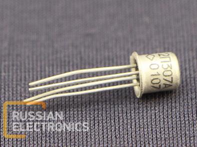
Siliconepitaxial-planar field-effect transistor with N-channel and P-N gate. Designed for use in input and output stages of high- and low-frequency amplifiers with high input impedance.
Case type: glass-metal with flexible terminals
Device type is indicated on its case
Mass not more than 0.5 g
Electrical parameters
| Noise ratio (at f=400 MHz, UDS=10 V, ID=5 mA), not more than, dB | 6 |
| Noise electromotive force (at f=1 kHz, UDS=10 V, UGs=0), not more than, nV/√Hz | 20 |
| Mutual transconductance (UDS=10 V, UGS=0, f=50..1500 Hz), mA/V at +25 oC at -60 oC at +125 oC | 4..9 4 2 |
| Drain residual current (at UDS=10 V, UGS=0), mA | 3..9 |
| Cut-off voltage (at UDS=10 V, ID=10 mkA), V | 0.5..3 |
| Gate leakage current, not more than at UGS=-10 V and +25 oC at UGS=-10 V and +125 oC at UGS=-30 V | 1 nA 1 mkA 10 mkA |
| Input capacitance (at UDS=10 V, UGS=0, f=10 MHz), not more than, pF | 5 |
| Input-to-output capacitance (at UDS=10 V, UGS=0, f=10 MHz), not more than, pF | 1.5 |
Operational limits
| Drain-to-source voltage, V | 25 |
| Gate-to-drain, gain-to-source voltage, V | 30 |
| Drain constant current, mA | 30 |
| Gate forward current, mA | 5 |
| Constant power dissipation1, mW at +60..+25 oC at +125 oC | 250 50 |
| Transistor structure temperature, oC | +140 |
| Ambient air temperature, oC | -60..+125 |
1At T>+25 oC maximum power dissipation can be calculated in accordance with the following formula:
PMAX=250-2(T-25) mW


