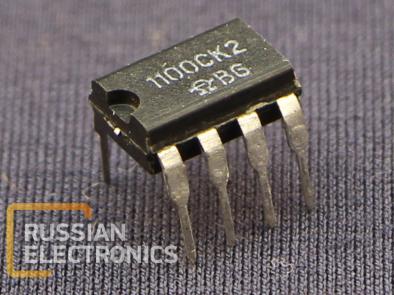
KR110SK2
Sample-and-hold device for analog signals.
Key features
| Power supply voltage, V | ±15 (gr. B), ±12 (gr.A) |
| Sampling time (inaccuracy 0.1 %, load capacitance 1000 pF), mks | 7 |
| Aperture delay, not more than, ns | 180 |
| Input voltage range, V | ±10 (gr.B), ±5 (gr.A) |
| External hold capacitor | |
| Input short-circuit protection | |
| Operating input compatible with TTL/CMOS logic |
Appliance:
· Together with ADC
· In DAC glitch stopper circuits
· In peak detectors
· In analog delay lines
· In synchronous access circuits and data distribution systems
Integral circuits hold the given input voltage after a corresponding command on LOGIC input and maintain the equal output voltage for a given period of time. The circuit contains of 4 main elements: input amplifier, hold device (external capacitor), output buffer and switching circuit.
The input amplifier is a high-impedance load for signal source and provides the current amplification for hold capacitor charge, acting like an input buffer.
In sample mode the hold capacitor output voltage follows the input signal (considering a minor delay and bandwidth limitations.
In hold mode the switch turns off and the hold capacitor holds the voltage, given before. Output buffer has a high impedance and prevents the hold capacitor early discharge. The switching circuit and its driver provide switching between sample and hold modes.
Rated power supply voltage ±12 V.
Case type 2101.8-1
Terminal assignment
| Label | Number | Function |
| LOGIC | 8 | Operating input (control) |
| UCC1 | 1 | Positive power supply voltage |
| OFFSET | 2 | Balance |
| UСС2 | 3 | Analog input |
| INPUT | 4 | Negative power supply voltage |
| OUT | 5 | Analog output |
| CH | 6 | Hold capacitor |
| LOGREF | 7 | Operating input threshold control |
You can order KR1100SK2 from us
Other products in IC’s, UNF modules, Microassemblies


